Sunday, July 26, 2015

Finally posting my barn doors (with a twist at the end)

I have been working on and off for the last 2 years on these barn doors to convert our dining room into a music room for my wife to work in.  I am just now getting around to finishing the last couple pieces of track and hardware and thought it would be worth sharing.

Finished doors closed and open...


First, I want everyone to take notice of the fact that there are 3 doors to span the opening.  This is not a normal configuration for barn doors.  This creates some interesting challenges as one door is set in front of the others.  Because of the unusual layout all the hardware was custom made using parts cobbled together from local stores.

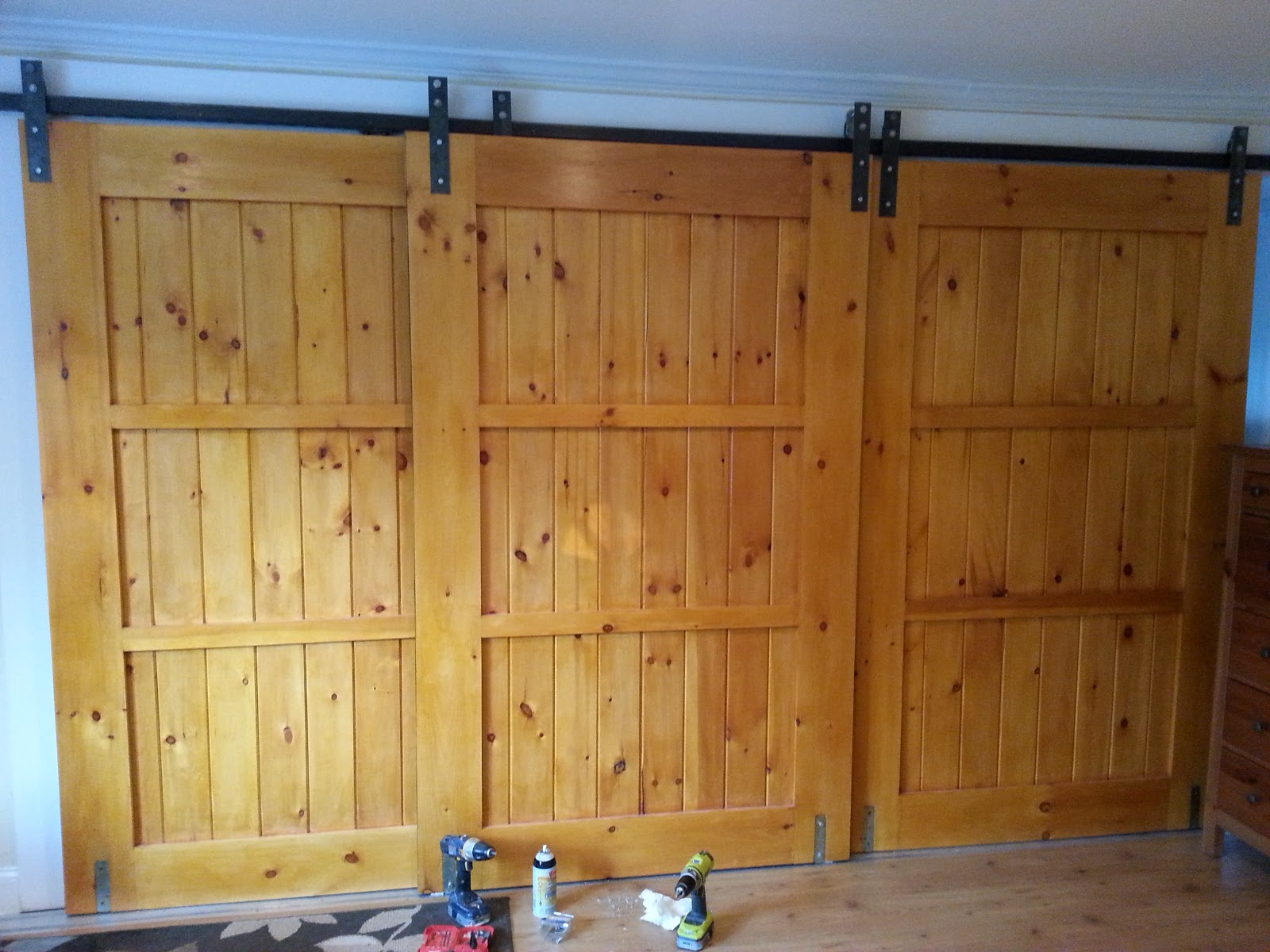
Secondly these are not ordinary barn doors.  These doors serve a dual purpose which I will get into later. (jump the the bottom if you are impatient)

Now for the build...

My first challenge was making the track to span the 17 feet of wall I needed.  I did this by brazing 2 sections of steel electrical channel conduit using a mapp gas and oxygen torch from harbor freight and bolted to a third rail for stability.  After brazing I went over the slag with an angle grinder to finish it for smooth motion on the top.

A coat of black spray paint, and heavy duty bolts at 2' intervals to secure it to the wall...


Next I began building the doors using interlocking pine boards like pictured here (tongue-groove-pine) all cut to approximately 80" long, glue and hammered together as the base slab 4' wide.  The side showing in the example image below was the back of the door, and gets a veneered later on in the steps.

(example image, not mine)

On top of the slab 6" pine face boards cut to the same dimensions as the slab (80" long for the sides, 3' long cross members).  This created a picture frame effect built on top, then thinner 2" pine boards crossing the width in the middle as shown at even spacing.  These were all nailed through the face into the slab of interlocking boards.  Belt clamps were used to hold it together while the glue dried.


Test fit against wall...

I took framing straps and bore out the existing holes using a stepped drill bit to give me a consistent template for the brackets, and a solid mating to the wood..  These were recessed into the top and bottom of the doors using a hand chisel, and the holes were counter sunk, and drilled through to take the hardware to hang the doors.


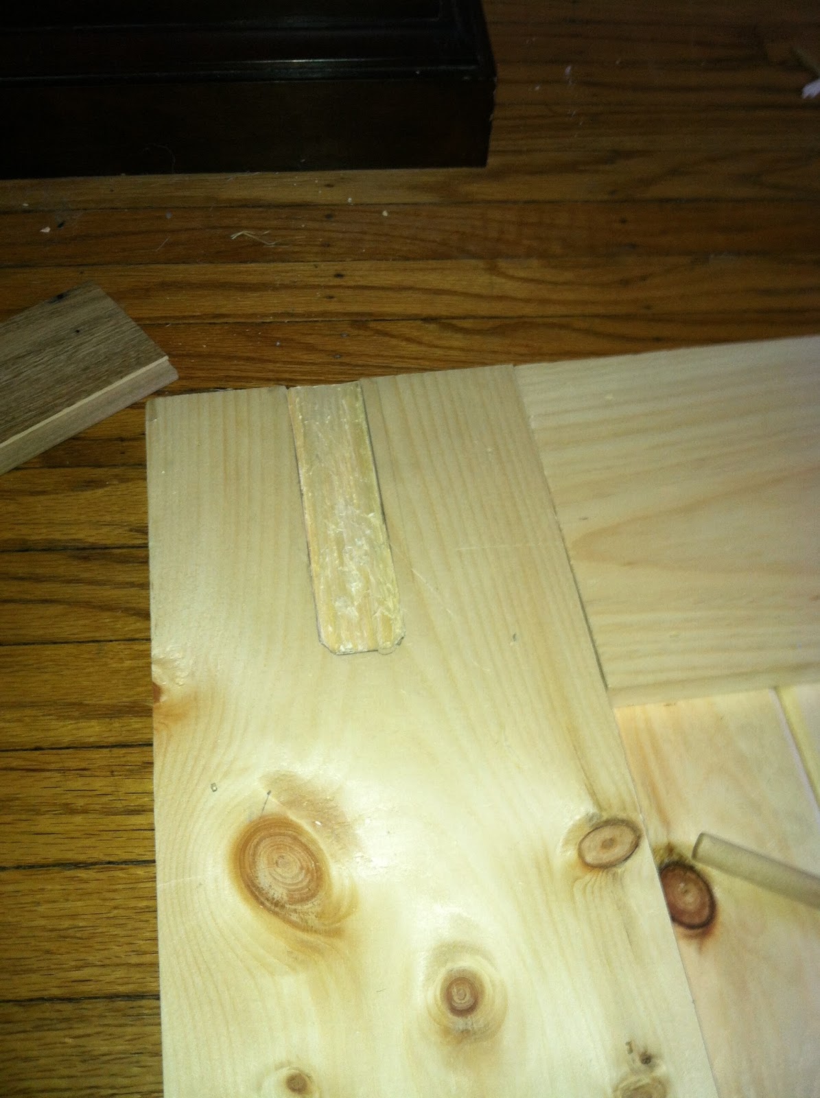
Captive nuts were hammered into the opposite sides 2 per bracket at the top and bottoms.


 It is important to note that the hardware for the rear door was offset to allow both doors overlap fully.


Brackets were cut out of 2" cold rolled steel using my chop saw, and fitted with pulley hardware as pictured to hold the track.


And since the front door cannot hold its weight by hanging from the top track, bearings were bolted into the bottom of the front door's metal framing strap and a pocket was further chiseled out behind the bracket to make room for it.  These run on an aluminum track I built up in the floor using flat strips of 2" aluminum covered with 1" and 2" as pictured below to make a channel.


Finally the backs were veneered using sand ply with construction adhesive, and sealed with shellac and spray varnish.  The edges and backs of the doors were trimmed with 1.5" black painted aluminum L extrusion.


Now for the second purpose of the doors, all three doors can take legs in the brackets that hold the hangers and they double as our dining room tables!


The hardware for the legs match the threading for the captive nuts on the opposite sides and can screw into the same holes as the hanging brackets.


This solves what we do with our tables while not in use for large parties, since we gave up the dining room to the wife's business.

Hope you enjoyed.

Tuesday, June 18, 2013

Just another R2D2 Birthday Cake Build

I went a little out of control this year with my son's 6th birthday cake.  He is a a big Star Wars fan, as all 6 year olds should be.  I figured I would document the build since it was more project build thank a cake.

I started by looking up pictures of R2D2, and quickly realized to do it correctly it really needed a custom stand.  This is what I started with.

The frame is wood and cardboard with a PVC pipe running up the middle.  The PVC is mainly structural support so the cake doesn't slide off the stand, but the choice for this size PVC wasn't completely random either

My wife was nice enough to bake six 9" round chocolate cakes for me.  These were of the standard Pillsbury (or similar) variety.

Next came alternating layers of cake and butter-cream icing.  The recipe for butter-cream is simple.  I do it from memory, but I used something like the one found here with just butter and no shortening.  http://www.wilton.com/recipe/Buttercream-Icing

This whole thing was topped with a cardboard ring to provide a crisp edge at the top.  The outside was then frosted with a modestly thick layer to make a cylindrical shape.

The whole thing is covered with fondant.  I make a marshmallow fondant myself to save time and money. http://www.wilton.com/recipe/Rolled-Marshmallow-Fondant

To make to top dome I added CMC powder to the marshmallow fondant.  This turns the fondant into gum paste, and turns the fondant hard after it dries.  This was then molded into the inside of a 9" semi-spherical bowl that was coated in vegetable spray and powdered sugar.


Rice crispy treats were used for the legs.  I didn't document this beforehand but here is a posthumous picture of the leg from the inside.

This was all assembled and decorated with fondant and black decorative icing.

This gets me to the part that made this more than just a cake.  the weekend before I was discussing the initial planning phase of this with some friends, and I joked that any R2D2 worth it's salt should be able to project Princess Leia.  This quickly escalated into a  review of the parts I had laying around and some test electronics.  First I needed the video to project, which I found unsurprisingly on youtube.


Next I pulled out my raspberry pi and pico projector, but quickly abandoned the raspberry pi as it was having trouble playing the video.  I landed on a netbook on the outside running VGA to the projector in the cake.  The PVC selected allowed all the cables to fit up and through the cake to the outside.  The setup looked like this.


For the finish touches I added a birthday message to the end of the Leia Message, and topped the cake with R2D2's head.


And a video showing the whole thing in action.


Friday, April 2, 2010

Soluble Thermo Polymers

Doing a little reading on Hackaday.com and one of the posts describes the polymers using to hold silicon wafers during milling.

Crystal Bond


Typical Applications:
  • Machining advanced ceramics.
  • Lapping and polishing optical components.
  • Dicing ceramic substrates and semiconductor wafers.
  • Dicing ferrites, glasses and piezoelectrics.
  • Dicing metal and optical single crystals.
  • Mounting cross-sections for electron microscopy.
  • Backfilling components for temporary mechanical support.

A couple interesting things about this:
-different material solvents (acetone, water, methanol)
-low softening point should allow for other plastics to adhere to the prior layers.

i think this may be useful for printing rafts or even as a support material assuming there is no significant shrinkage as it cools.

Any opinions before I purchase a stick?

Monday, March 22, 2010

MDF Secured


Made a little more progress this weekend on the RepStrap. Attached most of the MDF that will be on the frame, and i think the proof of concept build surface is going to work just fine.

This is the underside of my y-axis/build surface. It is basically just bearing supporting the carriage like a normal 4 wheeled cart. I am using 2 bearings per corner, but this could probably be reduced to 1.

The bearings i used are smaller than the fixit blocks so they were easy to mount. the support for side-to-side tray motion is provided by the slight lip of the fixit block pressed against the square rail, which you can make out in the 1st picture. So far this seems to work, there is very little wiggle in the bed, and it moved freely forward and backward. My hope is once the herringbone rack is printed and installed the tray will be further stabilized, and the tight tolerances will be less important.

Lastly, I managed to install the bottom tray that will mount the z-axis and potentially the stepper for the y-axis. I notched the MDF to allow the gear/pulley drive to clear the threaded rod on the bottom of the machine.


Thursday, March 18, 2010

Initial Assembly


Assembled the base frame last night. The PVC ends seem to be more than up to the task, and everything squared up nicely.

I am playing with square rails on the bottom axis. It should allow for floating trays, and when I have a functional printer I will upgrade to a rack and pinion configuration. My goal is to produce a repstrap that has removable trays that can be fed into and out of the machine automatically.

Auto feed trays open many possible avenues for production. Secondary machines can be added to perform subsequent steps in manufacturing as we produce more complicated designs. Simple examples would be a pick and place, or tray sorter.

This would allow for many different build surfaces quickly interchanged or longer rails clipped onto the ends to allow for longer build surfaces.

Thoughts? I am not very far along yet, so if anyone has concerns please raise them now.

Tuesday, March 16, 2010

Improvised Corner Bracket


I wanted to share my method for creating the corner brackets on my repstrap. It is not anything as clean looking as others have done, but so far it seems to have worked for me. My only concern is potential deformation of the PVC under strain, but so far it seems like it is rigid enough for the job.

It is just a piece of PVC pipe from a local hardware store ~$1.25. I cut it into 1" rings and marked where 3 intersected to create the desired holes for the triangular sides.

Monday, March 15, 2010

First Post

So, i have made some progress on my RepStrap and figured it was time to start a blog to share my progress.

It is based on the Reprap Mendel, but since I lack a functional 3d printer or the funds to purchase everything I have been cutting corners to get something working for as little money as possible.

The construction is based on the same corner blocks that BodgeIt is using on the Bertha, but I am not trying to as faithfully reproduce the Mendel. I hope to make some improvements to the existing Mendel design. Primarily, a y axis tray that is longer and can be fed into and out of the machine.

For electronics I am using an Arduino Mega and the Pololu Stepper Carriers.

I'll post pictures of my progress as appropriate.